
Relay Module Control
Control high-power devices remotely using relay modules with ESP32
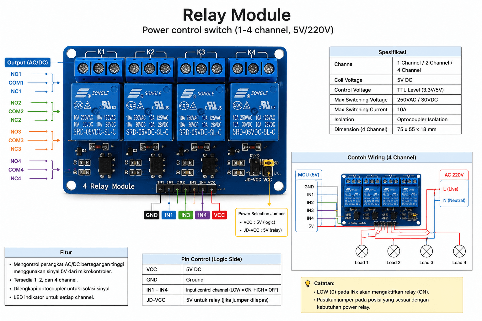
What is a Relay?
A relay is an electrically operated switch that allows low-voltage circuits (like ESP32 at 3.3V) to control high-voltage/high-current circuits (like 220V AC appliances). It provides electrical isolation between control and power circuits for safety.
Relay Module Specifications
Current Rating
Always check your specific relay module's current rating. Common ratings are 5A and 10A. Never exceed the rated current - add a safety margin (use only 80% of rated capacity for continuous operation).
Pin Configuration
Control Pins (Low Voltage Side)
| Pin | Function | ESP32 Connection |
|---|---|---|
| VCC | Power supply (3.3V or 5V) | 3.3V or 5V pin |
| GND | Ground | GND pin |
| IN1 | Control signal for relay 1 | GPIO 25 |
| IN2 | Control signal for relay 2 | GPIO 26 |
Power Terminals (High Voltage Side)
| Terminal | Name | Description |
|---|---|---|
| 1 | COM | Common - always connected to power source |
| 2 | NO | Normally Open - closed when relay activated |
| 3 | NC | Normally Closed - opens when relay activated |
Note: For most applications, use COM and NO terminals. The load is OFF when relay is inactive, ON when relay is activated.
Active Low vs Active High
How to Identify
Most Chinese relay modules have LED indicators. Connect power and leave IN pin floating or connected to VCC - if LED is ON, it's Active Low. If LED is OFF, it's Active High.
Basic Control Code
relay_basic.inocpp
// Define relay pins
#define RELAY1_PIN 25
#define RELAY2_PIN 26

void setup() {
  Serial.begin(115200);

  // Initialize relay pins as outputs
  pinMode(RELAY1_PIN, OUTPUT);
  pinMode(RELAY2_PIN, OUTPUT);

  // Initial state - all relays OFF
  // For Active Low modules:
  digitalWrite(RELAY1_PIN, HIGH);  // OFF
  digitalWrite(RELAY2_PIN, HIGH);  // OFF

  Serial.println("Relay control initialized");
}

void loop() {
  // Turn relay 1 ON
  Serial.println("Relay 1 ON");
  digitalWrite(RELAY1_PIN, LOW);   // For Active Low
  delay(3000);

  // Turn relay 1 OFF
  Serial.println("Relay 1 OFF");
  digitalWrite(RELAY1_PIN, HIGH);  // For Active Low
  delay(3000);

  // Turn relay 2 ON
  Serial.println("Relay 2 ON");
  digitalWrite(RELAY2_PIN, LOW);
  delay(3000);

  // Turn relay 2 OFF
  Serial.println("Relay 2 OFF");
  digitalWrite(RELAY2_PIN, HIGH);
  delay(3000);

  // Both relays ON
  Serial.println("Both relays ON");
  digitalWrite(RELAY1_PIN, LOW);
  digitalWrite(RELAY2_PIN, LOW);
  delay(3000);

  // Both relays OFF
  Serial.println("Both relays OFF");
  digitalWrite(RELAY1_PIN, HIGH);
  digitalWrite(RELAY2_PIN, HIGH);
  delay(3000);
}
Control via WiFi Commands
relay_wifi_control.inocpp
#include <WiFi.h>
#include <WebServer.h>

const char* ssid = "YOUR_WIFI_SSID";
const char* password = "YOUR_WIFI_PASSWORD";

#define RELAY1_PIN 25
#define RELAY2_PIN 26

WebServer server(80);

// Relay states
bool relay1State = false;
bool relay2State = false;

void setup() {
  Serial.begin(115200);

  // Initialize relays
  pinMode(RELAY1_PIN, OUTPUT);
  pinMode(RELAY2_PIN, OUTPUT);
  digitalWrite(RELAY1_PIN, HIGH);  // OFF
  digitalWrite(RELAY2_PIN, HIGH);  // OFF

  // Connect to WiFi
  WiFi.begin(ssid, password);
  while (WiFi.status() != WL_CONNECTED) {
    delay(500);
    Serial.print(".");
  }

  Serial.println("\nConnected to WiFi");
  Serial.print("IP: ");
  Serial.println(WiFi.localIP());

  // Setup web server routes
  server.on("/", handleRoot);
  server.on("/relay1/on", []() { controlRelay(1, true); });
  server.on("/relay1/off", []() { controlRelay(1, false); });
  server.on("/relay2/on", []() { controlRelay(2, true); });
  server.on("/relay2/off", []() { controlRelay(2, false); });
  server.on("/status", handleStatus);

  server.begin();
  Serial.println("Web server started");
}

void loop() {
  server.handleClient();
}

void controlRelay(int relayNum, bool state) {
  int pin = (relayNum == 1) ? RELAY1_PIN : RELAY2_PIN;

  // Active Low: LOW = ON, HIGH = OFF
  digitalWrite(pin, state ? LOW : HIGH);

  if (relayNum == 1) {
    relay1State = state;
  } else {
    relay2State = state;
  }

  String response = "Relay " + String(relayNum) + " turned " + (state ? "ON" : "OFF");
  server.send(200, "text/plain", response);

  Serial.println(response);
}

void handleRoot() {
  String html = "<html><body>";
  html += "<h1>Gridova Relay Control</h1>";
  html += "<p>Relay 1: " + String(relay1State ? "ON" : "OFF") + "</p>";
  html += "<a href='/relay1/on'><button>Turn ON</button></a> ";
  html += "<a href='/relay1/off'><button>Turn OFF</button></a><br><br>";
  html += "<p>Relay 2: " + String(relay2State ? "ON" : "OFF") + "</p>";
  html += "<a href='/relay2/on'><button>Turn ON</button></a> ";
  html += "<a href='/relay2/off'><button>Turn OFF</button></a>";
  html += "</body></html>";

  server.send(200, "text/html", html);
}

void handleStatus() {
  String json = "{\"relay1\":" + String(relay1State ? "true" : "false");
  json += ",\"relay2\":" + String(relay2State ? "true" : "false") + "}";

  server.send(200, "application/json", json);
}
Access the web interface at: http://ESP32_IP_ADDRESS/
Integration with Gridova API
gridova_relay_integration.inocpp
#include <WiFi.h>
#include <HTTPClient.h>
#include <ArduinoJson.h>

const char* serverUrl = "https://api.gridova.com/relay/control";
const char* deviceId = "ROOM_001";
unsigned long lastCheckTime = 0;
const unsigned long checkInterval = 5000; // Check every 5 seconds

#define RELAY1_PIN 25
#define RELAY2_PIN 26

void setup() {
  Serial.begin(115200);

  pinMode(RELAY1_PIN, OUTPUT);
  pinMode(RELAY2_PIN, OUTPUT);
  digitalWrite(RELAY1_PIN, HIGH);
  digitalWrite(RELAY2_PIN, HIGH);

  // Connect to WiFi
  WiFi.begin("SSID", "PASSWORD");
  while (WiFi.status() != WL_CONNECTED) {
    delay(500);
  }

  Serial.println("Connected!");
}

void loop() {
  unsigned long currentTime = millis();

  // Check server for relay commands
  if (currentTime - lastCheckTime >= checkInterval) {
    checkRelayCommands();
    lastCheckTime = currentTime;
  }
}

void checkRelayCommands() {
  if (WiFi.status() != WL_CONNECTED) return;

  HTTPClient http;
  String url = String(serverUrl) + "?device_id=" + deviceId;

  http.begin(url);
  int httpCode = http.GET();

  if (httpCode == 200) {
    String payload = http.getString();

    // Parse JSON response
    StaticJsonDocument<256> doc;
    DeserializationError error = deserializeJson(doc, payload);

    if (!error) {
      bool relay1 = doc["relay1"];
      bool relay2 = doc["relay2"];

      // Update relay states
      digitalWrite(RELAY1_PIN, relay1 ? LOW : HIGH);
      digitalWrite(RELAY2_PIN, relay2 ? LOW : HIGH);

      Serial.printf("Updated: Relay1=%s, Relay2=%s\n",
                    relay1 ? "ON" : "OFF",
                    relay2 ? "ON" : "OFF");
    }
  }

  http.end();
}

// Function to report relay state to server
void reportRelayState() {
  HTTPClient http;
  http.begin(serverUrl);
  http.addHeader("Content-Type", "application/json");

  StaticJsonDocument<256> doc;
  doc["device_id"] = deviceId;
  doc["relay1"] = (digitalRead(RELAY1_PIN) == LOW);
  doc["relay2"] = (digitalRead(RELAY2_PIN) == LOW);
  doc["timestamp"] = millis();

  String jsonString;
  serializeJson(doc, jsonString);

  int httpCode = http.POST(jsonString);
  Serial.printf("Report sent: %d\n", httpCode);

  http.end();
}
High Voltage Wiring
Electrical Safety Warning
This section involves working with mains voltage (220V AC). Only qualified personnel should perform these connections. Improper wiring can cause fire, electric shock, or death.
Wiring Diagram Explanation
AC Mains (220V) → Circuit Breaker → Relay COM
Relay NO → Load (Appliance) → Neutral
Step-by-step:
- Disconnect all power sources
- Connect Live wire from breaker to relay COM terminal
- Connect relay NO terminal to appliance Live wire
- Connect appliance Neutral directly to mains Neutral
- Connect Ground/Earth to appliance chassis
- Secure all connections with proper wire nuts or terminals
- Install in proper electrical enclosure
- Test with multimeter before applying power
Safety Considerations
Advanced: Failsafe Code
relay_failsafe.inocpp
#include <esp_task_wdt.h>

#define RELAY1_PIN 25
#define MAX_ON_TIME 3600000  // 1 hour in milliseconds
#define WDT_TIMEOUT 10       // 10 seconds

unsigned long relay1OnTime = 0;
bool relay1Active = false;

void setup() {
  Serial.begin(115200);

  pinMode(RELAY1_PIN, OUTPUT);
  digitalWrite(RELAY1_PIN, HIGH);  // OFF by default (failsafe)

  // Setup watchdog timer
  esp_task_wdt_init(WDT_TIMEOUT, true);
  esp_task_wdt_add(NULL);

  Serial.println("Failsafe relay control initialized");
}

void loop() {
  // Reset watchdog
  esp_task_wdt_reset();

  // Check maximum ON time
  if (relay1Active) {
    if (millis() - relay1OnTime > MAX_ON_TIME) {
      Serial.println("Max ON time reached - turning OFF");
      setRelay1(false);
    }
  }

  // Your control logic here
  delay(100);
}

void setRelay1(bool state) {
  digitalWrite(RELAY1_PIN, state ? LOW : HIGH);
  relay1Active = state;

  if (state) {
    relay1OnTime = millis();
    Serial.println("Relay 1 ON");
  } else {
    Serial.println("Relay 1 OFF");
  }

  // Log to EEPROM or send to server
  logRelayState(1, state);
}

void logRelayState(int relay, bool state) {
  // Save to EEPROM or send to server
  Serial.printf("LOG: Relay %d = %s at %lu\n",
                relay, state ? "ON" : "OFF", millis());
}