
ESP32 Development Board
Setup and configure ESP32 as the main controller for Gridova IoT system
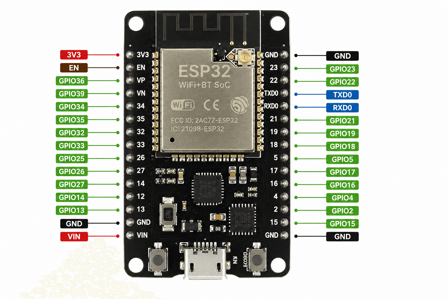
Why ESP32?
ESP32 offers dual-core processing, built-in WiFi/Bluetooth, multiple GPIO pins, and low power consumption - perfect for IoT applications like Gridova.
ESP32 Specifications
Arduino IDE Setup
1. Install Arduino IDE
Download and install Arduino IDE 1.8.x or 2.x from the official website.
Download Linkbash
https://www.arduino.cc/en/software2. Add ESP32 Board Manager URL
Open Arduino IDE, go to File → Preferences, and add this URL:
Board Manager URLtext
https://raw.githubusercontent.com/espressif/arduino-esp32/gh-pages/package_esp32_index.json3. Install ESP32 Board
Go to Tools → Board → Boards Manager, search for "esp32" and install.
4. Select Board and Port
- Board: ESP32 Dev Module
- Upload Speed: 921600
- Port: Select your COM port (e.g., COM3, COM5)
Required Libraries
Install these libraries via Sketch → Include Library → Manage Libraries:
Basic WiFi Connection Code
wifi_basic.inocpp
#include <WiFi.h>

// WiFi credentials
const char* ssid = "YOUR_WIFI_SSID";
const char* password = "YOUR_WIFI_PASSWORD";

void setup() {
  Serial.begin(115200);
  delay(1000);

  // Connect to WiFi
  Serial.println("Connecting to WiFi...");
  WiFi.begin(ssid, password);

  while (WiFi.status() != WL_CONNECTED) {
    delay(500);
    Serial.print(".");
  }

  Serial.println("");
  Serial.println("WiFi connected!");
  Serial.print("IP address: ");
  Serial.println(WiFi.localIP());
}

void loop() {
  // Check WiFi connection
  if (WiFi.status() != WL_CONNECTED) {
    Serial.println("WiFi disconnected. Reconnecting...");
    WiFi.reconnect();
  }
  delay(10000);
}
HTTP POST Request Example
Send sensor data to Gridova backend API:
http_post_example.inocpp
#include <WiFi.h>
#include <HTTPClient.h>
#include <ArduinoJson.h>

const char* serverUrl = "https://api.gridova.com/sensor-data";
const char* apiKey = "YOUR_API_KEY";

void sendSensorData(float voltage, float current, float power) {
  if (WiFi.status() == WL_CONNECTED) {
    HTTPClient http;

    http.begin(serverUrl);
    http.addHeader("Content-Type", "application/json");
    http.addHeader("Authorization", "Bearer " + String(apiKey));

    // Create JSON payload
    StaticJsonDocument<256> doc;
    doc["device_id"] = "ESP32_001";
    doc["voltage"] = voltage;
    doc["current"] = current;
    doc["power"] = power;
    doc["timestamp"] = millis();

    String jsonString;
    serializeJson(doc, jsonString);

    // Send POST request
    int httpResponseCode = http.POST(jsonString);

    if (httpResponseCode > 0) {
      Serial.printf("HTTP Response: %d\n", httpResponseCode);
      String response = http.getString();
      Serial.println(response);
    } else {
      Serial.printf("Error: %s\n", http.errorToString(httpResponseCode).c_str());
    }

    http.end();
  }
}

void loop() {
  // Read sensor values (example)
  float voltage = 220.5;
  float current = 2.8;
  float power = voltage * current;

  sendSensorData(voltage, current, power);
  delay(5000); // Send every 5 seconds
}
GPIO Pin Configuration
Recommended GPIO pins for Gridova hardware connections:
| Component | ESP32 Pin | Function |
|---|---|---|
| PZEM TX | GPIO 16 (RX2) | UART receive from PZEM |
| PZEM RX | GPIO 17 (TX2) | UART transmit to PZEM |
| Relay 1 | GPIO 25 | Digital output for relay control |
| Relay 2 | GPIO 26 | Digital output for relay control |
| Status LED | GPIO 2 | Built-in LED indicator |
| Button | GPIO 0 | Boot/flash button (input) |
Important Notes
- Avoid using GPIO 6-11 (connected to flash memory)
- GPIO 34-39 are input-only pins
- Some pins have pull-up/pull-down resistors by default
- Always use 3.3V logic level for GPIO communication